Advanced settings
The rare design inputs with sound defaults — the ways in, the window, what each pill means, every setting and how a project keeps them.
Advanced settings holds the rare inputs with sound defaults: the limits the design checks judge against, the cable sizes, the land warnings, the BOM's shared numbers. A change is for this project only. Most projects leave them alone.
Ways in
| From | Opens on |
|---|---|
| File ▸ Advanced settings…, reading "Advanced settings… (N changed)" when N is more than 0 | The window |
| The ribbon chip "Advanced settings · N changed" | The changed settings only |
| Edit… on the Summary view's note of changed settings | The changed settings only |
| Limits… on the Checks view | Checks and limits |
| Advanced… on the Cables card, beside "all at defaults" or "N changed" | Checks and limits |
| Edit… on the BOM panel's Profile card | BOM |
| A setting's row in the list of changes | The changed settings only, or the setting's group once it is back at its default |
The ribbon chip shows only while a setting is changed. An orange dot on it marks a setting that differs from the last run. All N lines in the BOM's Line card changes a BOM setting in place, without opening the window.

The window
A strip across the top reads "This project only. Defaults come from SolarLayout's standard list and the project's BOM profile.", with a chip, "All at defaults" or "N changed".
- Left: the groups, each with a note, such as "12 settings", "N changed" or "From the BOM profile", and "N matches" during a search. A gold dot marks a group with edits not applied yet.
- Right: Search settings, Changed only and Reset this group, then the settings.
- A setting's row: its label and help line; a pill saying what a change does; the check it feeds, if any; the field with its unit; "default 2.0 %" beside it, "was 2.0 %" while an edit is held, and the range when the value is not valid; and an arrow that puts it back, with the tooltip "Back to default 2.0 %".
- Footer: a count such as "1 setting differs from its default" or "1 edit · 1 sizes cables"; Cancel; and the gold button, which names its effect: Apply, Apply 2 changes or Apply 1 change · layout out of date. A reason stands beside it when it is disabled: "Nothing to apply", "Fix MV voltage drop: 0.1–10 %".
Edits are held until you click the button, and Cancel drops them.
What a change does
Each setting carries a pill.
| Pill | What a change does |
|---|---|
| Sizes cables · Generate again | Makes the layout out of date at once, with a row of its own in the list of changes, such as "MV voltage drop 2.0 % → 3.0 %". Change it back and the layout is current. It takes effect at the next Generate Layout; the checks use the last run's value until then |
| Checks · applies now | The layout stays current. The design checks run again straight away, and an open Export deliverables window follows |
| BOM · applies now | The layout stays current. Only the bill of materials recounts |
| Clean boundary · next review | Nothing changes yet. The next boundary review reads it |
| Yield · run the energy calculation again | The layout stays current, and an energy result on screen stays as it was calculated. Click Calculate Energy again to apply the value |
Every setting
The Pill column gives each pill's first words.
Checks and limits
| Setting | Default | Range | Pill | Check | Help line |
|---|---|---|---|---|---|
| DC string voltage drop | 1.5 % | 0.1–10 | Sizes cables | E-08 | String cable size is picked to stay within this. |
| LV feeder drop limit | 2.5 % | 0.1–10 | Sizes cables | E-02 | Inverter → ACCB: size A within this drop, else size B. |
| Plant LV drop budget | 1.5 % | 0.1–10 | Checks | E-02 | Average over all feeders, by current. A warning only. |
| MV voltage drop | 2.0 % | 0.1–10 | Sizes cables | E-02 | MV runs are added until each stays within this. |
| DC trunk parallel runs | 2 runs | 1–10 | Checks | E-12 | A trunk that needs more runs than this is flagged. |
| IDT loading | 100 % | 50–150 | Checks | E-01 | Load allowed, as a share of the standard rating. |
| Inverter DC:AC band | ± 15 % | 1–50 | Checks | E-03 | Flags inverters this far from the plant's own ratio. |
| Tables outside arrester cover | 0 tables | 0–10000 | Checks | E-09 | Tables allowed outside every arrester's circle. |
| Trenches outside the plant or under tables | 0 runs | 0–1000 | Checks | E-07 | Trench runs allowed in those places. |
| Land account closure | ± 0.01 ha | 0.01–1 | Checks | R-05 | How far the land account may be off the site area. |
| Drawn vs scheduled trench | ± 0.5 % | 0.1–10 | Checks | R-06 | How far drawn trench may differ from the schedule. |
| S1 cable totals against the takeoff | ± 0.5 % | 0.1–10 | Checks | R-04 | How far S1's cable metres may differ from the takeoff. |
Cables
| Setting | Default | Range | Pill | Check | Help line |
|---|---|---|---|---|---|
| String cable size | 4 mm² | 4–50 | Sizes cables | E-08 | Each string's own cable, at least this size. |
| Y pair cable size | 6 mm² | 4–50 | Sizes cables | E-08 | Each Y pair's cable; larger only if its current needs it. |
Clean boundary
| Setting | Default | Range | Pill | Help line |
|---|---|---|---|---|
| Outer boundary over its plots | 1.25 × | 1.01–10 | Clean boundary | Warn when an outer boundary is this many times its plots. |
| Survey map picked | 50 % | 1–100 | Clean boundary | Warn when the picked parcels cover this share of the map. |
| Plots of the file's drawing | 5.0 % | 0.1–100 | Clean boundary | Warn when the plots cover less than this of the drawing. |
Communication
| Setting | Default | Range | Pill | Help line |
|---|---|---|---|---|
| RS485: devices per chain | 20 devices | 1–256 | Sizes cables | A block's RS485 chains hold at most this many devices. |
| RS485: chain length | 1200 m | 50–5000 | Sizes cables | A block's RS485 chains are at most this long. |
Yield
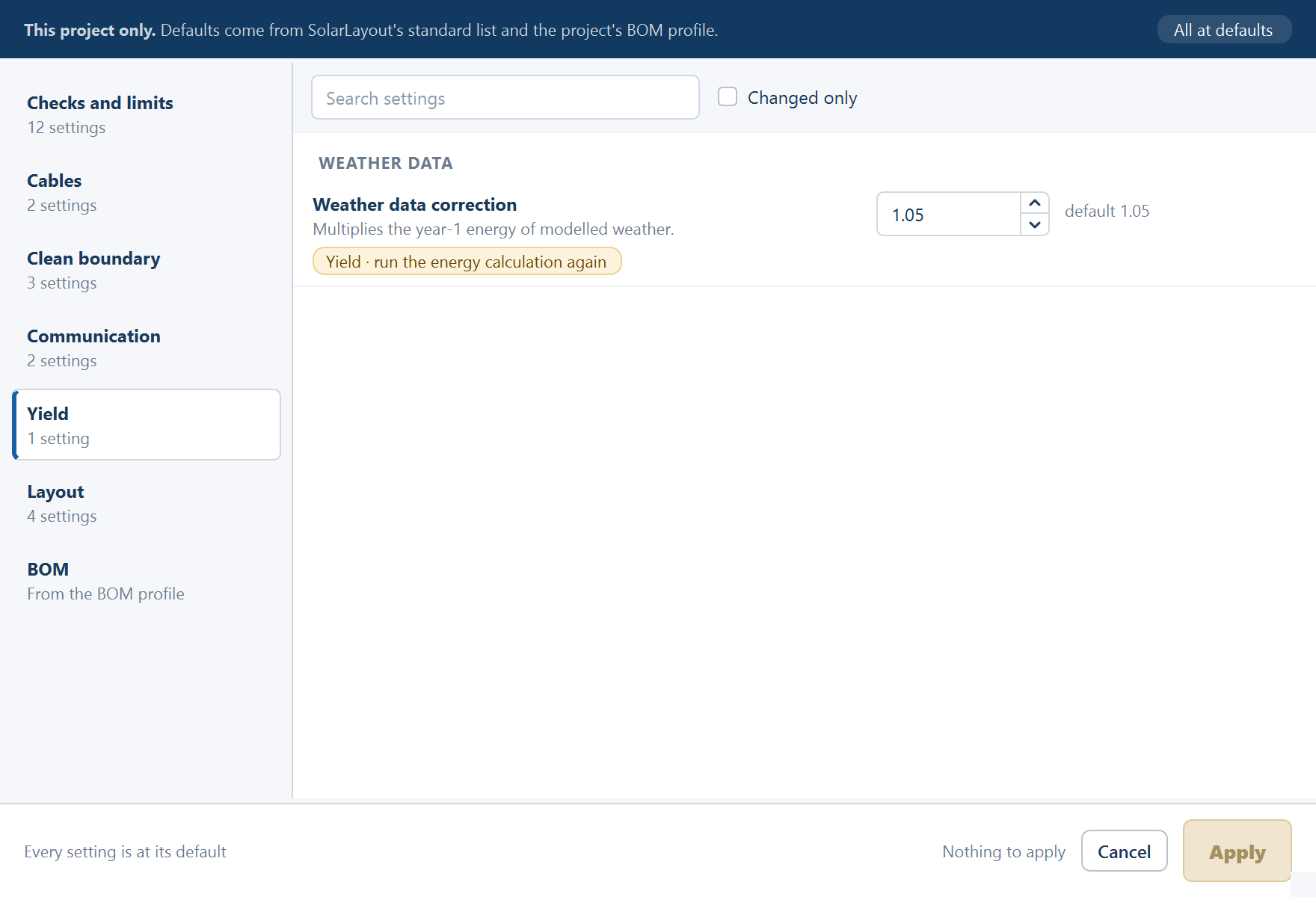
| Setting | Default | Range | Pill | Help line |
|---|---|---|---|---|
| Weather data correction | 1.05 | 0.8–1.3 | Yield | Multiplies the year-1 energy of modelled weather. |
Layout
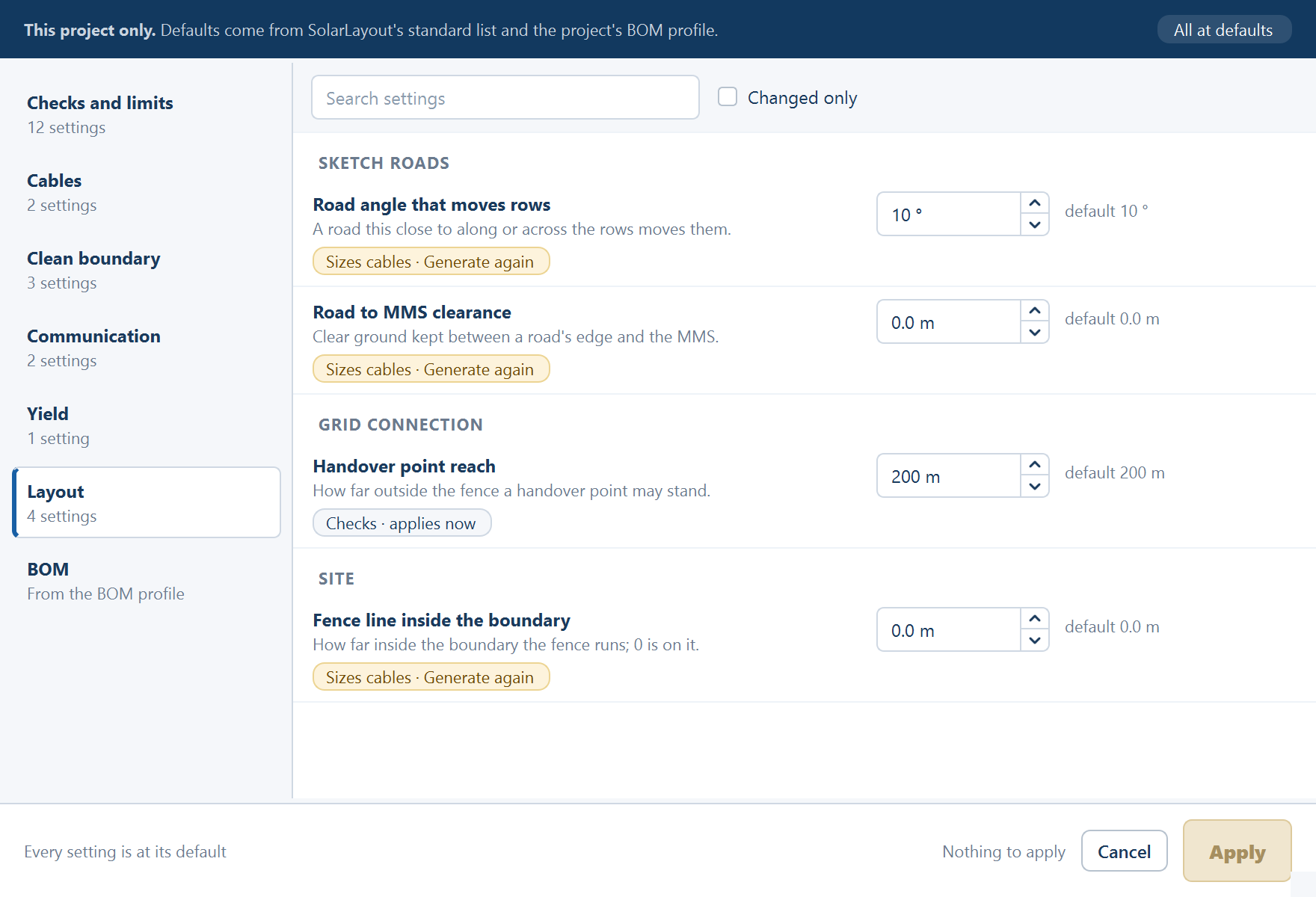
| Setting | Default | Range | Pill | Help line |
|---|---|---|---|---|
| Road angle that moves rows | 10 ° | 0–45 | Sizes cables | A road this close to along or across the rows moves them. |
| Road to MMS clearance | 0.0 m | 0–10 | Sizes cables | Clear ground kept between a road's edge and the MMS. |
| Handover point reach | 200 m | 0–5000 | Checks | How far outside the fence a handover point may stand. |
| Fence line inside the boundary | 0.0 m | 0–50 | Sizes cables | How far inside the boundary the fence runs; 0 is on it. |
The two road settings govern what a road drawn in Sketch Mode does to the rows. The handover point is described on Grid connection.
BOM
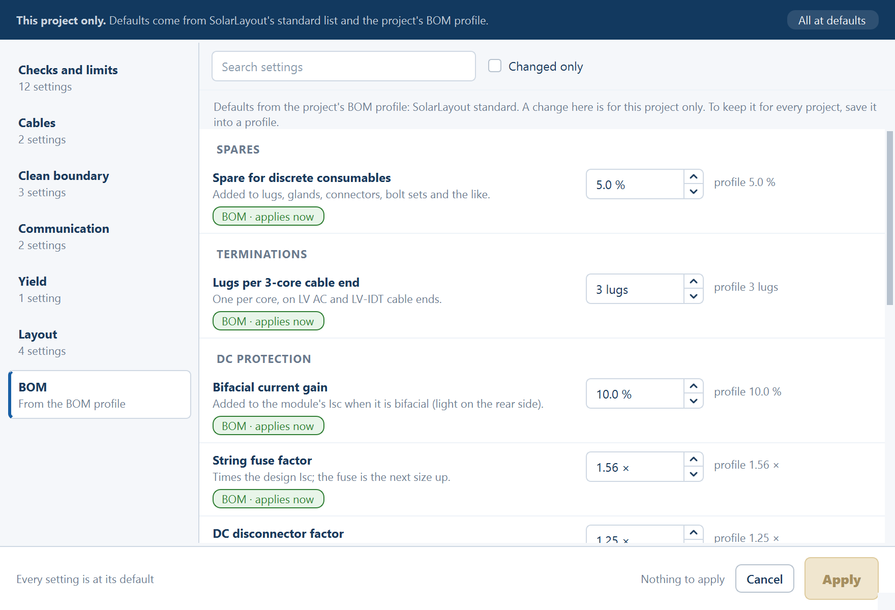
Numbers several BOM lines share. Their defaults come from the project's BOM profile, and the group's note says so: "Defaults from the project's BOM profile: <name>. A change here is for this project only. To keep it for every project, save it into a profile." Each carries the pill BOM · applies now, and a second line under the default, "used by N lines". See BOM profiles.
| Setting | Default | Range | Help line |
|---|---|---|---|
| Spare for discrete consumables | 5.0 % | 0–50 | Added to lugs, glands, connectors, bolt sets and the like. |
| Lugs per 3-core cable end | 3 lugs | 1–6 | One per core, on LV AC and LV-IDT cable ends. |
| Bifacial current gain | 10.0 % | 0–30 | Added to the module's Isc when it is bifacial (light on the rear side). |
| String fuse factor | 1.56 × | 1–3 | Times the design Isc; the fuse is the next size up. |
| DC disconnector factor | 1.25 × | 1–2 | Times the strings per SMB and the design Isc; the next size up. |
| String fuse sizes | 15, 20, 25, 30, 32, 50, 63 A | each 1–200 | The standard fuse sizes to choose from. |
| DC disconnector sizes | 250, 320, 400, 500, 630 A | each 50–2000 | The standard DC disconnector sizes to choose from. |
| MV cable drum length | 500 m | 50–2000 | One drum's length of MV cable; a run longer than a drum needs a straight joint per extra drum, per parallel cable. |
| Concrete block spacing | 0.8 m | 0.3–3 | Cable laid above ground rests on a concrete block every this many metres. |
| Cable tie spacing | 0.50 m | 0.1–2 | DC cable is tied to the table or tracker every this many metres. |
Where changes show
- The Summary view shows a note above the sheet: "Changed in Advanced settings: MV voltage drop 3.0 % (default 2.0 %) · …" with Edit…. It lists design settings, not BOM settings.
- The ribbon chip and the menu item carry the count.
- The design report prints the settings and limits, each marked default or changed in this project. See The design report.
How a project keeps them
The project file keeps the values off their defaults, and a change marks the project as changed. When a project opens, a saved value that can't be used is dropped, and a box titled Advanced settings had problems lists each one under "Some saved settings couldn't be used:".
| The box says | Meaning |
|---|---|
| "Advanced settings: 'x' is not a setting this version knows, so it was left out." | The file names a setting this version doesn't have |
| "… is not a number, so … is used." | The saved value is unreadable; the default stands |
| "… is outside …, so … is used." | The saved value is out of range; the default stands |
| "Advanced settings: the project's section is from a newer version, so every setting is at its default." | The file was saved by a later version of the application |
See Saving and reopening projects.
Where to go next
Out-of-date results
How the application knows a layout differs from its inputs, everything that says so, the exports it holds back meanwhile, and how the state clears.
Which boundary file to use
The three kinds of boundary file the application accepts, what each one carries, and how the Input Boundary File card on the Site tab reads them.