Lightning arresters
How arresters are placed on a coverage grid, what each one clears from the layout, and the settings that control the radius and the footprint.
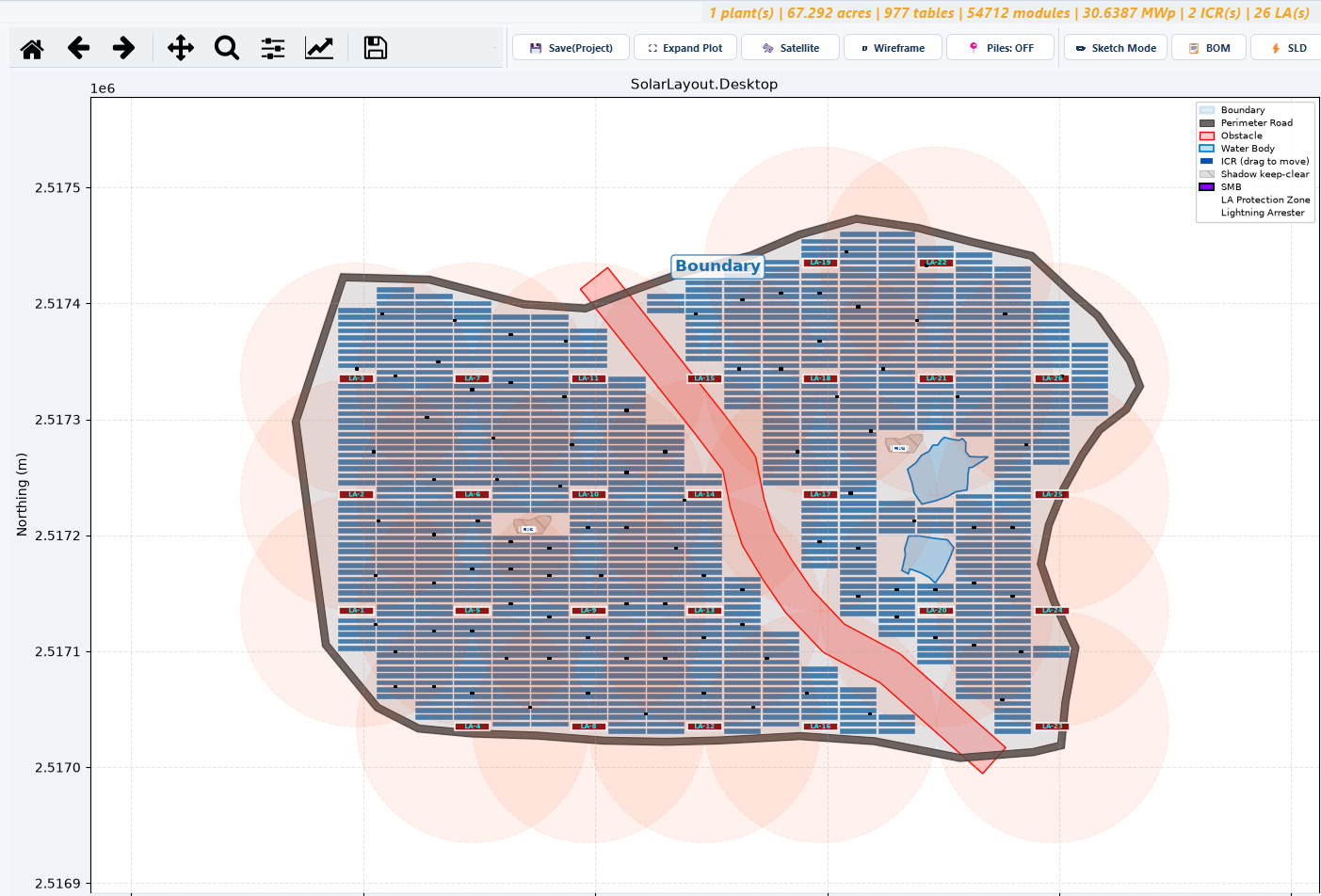
An LA — lightning arrester — is a mast that protects a circular area of ground around it against a direct strike. When you ask for them, the application places arresters across the plant on a grid sized so that every part of the layout falls inside at least one protected circle, then clears whatever module tables the arrester structure itself stands on.
Arresters are off by default. Nothing about the layout changes until you tick them on, and on a fixed-tilt plant turning them on reduces capacity — which is why the decision belongs to you rather than to a default.
Turning arresters on
Both settings live in the Site Parameters group of the input panel. They are read when you click Generate Layout; arresters are placed near the end of the run, after the module tables and the inverter control rooms are already down.
| Field | Default | Range | What it does |
|---|---|---|---|
| Place Lightning Arresters | off | — | Turns arrester placement on for the run. The radius field below stays greyed out until this is ticked. |
| LA protection radius | 100.0 | 10.0–500.0 | The radius, in metres, of the circle a single arrester protects. It also sets the spacing of the grid the arresters sit on. |
See Site parameters for the rest of that group.
What happens when arresters are off
No arresters are placed, no ground is reserved for them, and module tables fill the whole usable area — the plant boundary shrunk inward by the perimeter road width, with obstructions and terrain exclusions subtracted. The summary's LA column reads zero.
You can still add arresters individually by hand. In Sketch Mode the ➕ LA tool drops one wherever you click, and it clears the tables under its footprint exactly as an automatic one does. Leaving Sketch Mode recomputes the plant's module count, capacity and arrester count, so the summary follows your edits. See Sketch Mode.
The coverage model
This is the part worth understanding before you change anything, because every other consequence — how many arresters you get, how much capacity you lose, where the masts land — follows from it.
Two rules define it:
- Each arrester protects a circle of the LA protection radius, measured from the arrester's own centre.
- Arresters sit on a square grid whose spacing equals that radius. Not twice the radius, not the widest spacing the geometry would tolerate — the spacing is the radius, whatever radius you set.
Because the spacing equals the radius, neighbouring circles overlap heavily and every point of the grid interior is comfortably inside at least one circle.
Why the spacing equals the radius
The worst-served point inside a square grid cell is the centre of the cell — the point farthest from all four arresters around it. For a grid whose spacing equals the radius, that worst-case gap works out at the radius × √2 ⁄ 2, or about 0.707 of the radius. It is inside the protected circle with roughly 29 % of the radius still in hand, and that margin is the minimum overlap between neighbouring circles anywhere on the grid.
The margin is the whole point. A wider grid would still cover the cell centres on paper, but only just, and coverage would then depend on the grid landing neatly on the site, on the boundary not clipping positions away, and on the radius you typed being achieved in practice by the mast you actually build. Setting the spacing equal to the radius is the conservative choice: the circles overlap rather than meet, so the protection survives a ragged edge and a dropped position.
Which grid positions are kept
Only grid positions whose centre lies inside the usable area are kept. An arrester is therefore never placed on the perimeter road, in a water body, inside a transmission line or canal corridor, or on ground excluded by the slope limits. The consequence is visible on the plot: the arrester grid is regular across the middle of the plant and ragged wherever the boundary or an obstruction cuts into it.
Completing the coverage
Dropping positions at the edges would leave outlying tables unprotected, so a second pass fixes it. Every table is measured against every arrester already placed. Any table whose centre is farther than the protection radius from every arrester gets an extra arrester, placed at the nearest valid position to it.
Coverage is therefore completed rather than left with a hole. On a compact rectangular site the second pass adds nothing. On a long, thin or awkwardly notched site it adds the handful of arresters the regular grid could not reach, and those are the ones you will see sitting off the grid lines.
The footprint, and what it clears
The circle is the protection. The footprint is the physical structure, and it differs by mounting type — which matters, because on one of the two it costs you modules.
The arrester occupies a rectangle of 30 m east–west × 7 m north–south. Any MMS table overlapping that rectangle is removed, and the plant's module count and DC capacity are recomputed afterwards from what survives.
So on a fixed-tilt plant, arresters cost capacity. How much depends on how many positions the grid produces, which depends on the protection radius and the size and shape of the site. Generate once without arresters and once with them, and compare the DC(MWp) column in the summary to see the exact figure for your site rather than an estimate.
- What it shows
- A zoomed tracker view showing the small square arrester markers positioned in the gaps between tracker columns, with no tracker units removed.
- How to get there
- A tracker mode with arresters enabled. Zoom in far enough that the markers are visible.
- Callouts to add
- Outline one marker and label the inter-row gap it sits in.
Because arresters clear tables on a fixed-tilt plant and clear nothing on a tracker plant, a capacity comparison between the two mounting types is not like-for-like unless arresters are set the same way in both runs.
Raising or lowering the protection radius
The radius does two jobs at once — it sizes the protected circle and the grid spacing — so changing it changes the arrester count more than you might expect.
| Change | Arresters placed | Overlap between circles | Tables cleared (fixed tilt) |
|---|---|---|---|
| Raise the radius | Fewer | Less | Fewer |
| Lower the radius | More | More | More |
Two things to hold in mind:
- The grid spacing follows the radius in both directions, so the number of positions changes with the area of a grid cell, not with its side. A modest change to the radius moves the arrester count noticeably.
- The radius is a claim about the mast you will build. Raising it to thin out the grid only reduces cost if the installed arrester genuinely protects that far. The application takes the number you give it and does not check it against a protection standard.
Arrester height and pile
Two further arrester fields sit in the Structures & Shadow group, alongside the building footprints:
| Field | Default | Range | Unit |
|---|---|---|---|
| LA height | 9.0 | 0.0–100.0 | m |
| LA pile Ø | 0.3 | 0.0–5.0 | m |
Neither field feeds anything. They are read from the panel and go no further: the height does not size the footprint, cast a shadow or clear a table; the pile diameter does not reach the pile count, the materials list or any export; and neither value is kept when the project is saved, so both come back at the figures above. Enter the mast you intend to build if it helps you keep track, and carry the real figures in your structural and civil documents.
The arrester is also not one of the structures whose shadow clears tables. The Clear tables inside shadows option in the same group names the ICR, the MCR and placed objects, and nothing else — so a taller mast never costs you a module. What clears tables is the arrester's own footprint, above. See Structures and shadow for the shadow window and what it does.
Reading arresters on the plot and in the outputs
- On the plot. The Lightning Arresters switch is OFF by default, even on a run that placed them — switch it on to see the masts and their protection circles. Arresters are drawn dark red.
- In the summary. The LA column reports the arrester count for each plant, and the TOTAL row aggregates it. Because arresters are placed after the tables, the module and capacity columns on the same row already account for the tables the arresters cleared.
- In the CAD drawing. The arrester symbols are written to their own
LAlayer, present only when arresters were actually placed. See CAD drawing export. - In the Google Earth file. Arresters are exported with the rest of the plant.
Arresters and cleaning robots
An arrester footprint on a fixed-tilt plant interrupts the run of tables a cleaning robot drives along. The robot sizing tool lists every gap too wide for a standard inter-table bridge, separating gaps blocked by equipment — arresters, buildings, obstructions — from gaps in open ground, so you can decide which to bridge. See Robotic module cleaning.
Placing an arrester by hand
Use this to add protection the grid did not reach, or to place arresters on a plant generated with the option off.
Generate the layout
Hand placement acts on an existing layout, so generate first.
Switch Sketch Mode on
The ✏ Sketch Mode button on the plot toolbar reveals the tool palette.
Pick ➕ LA and click a position
Each click places one arrester and clears the tables under its footprint.
Leave Sketch Mode
The plant totals — modules, capacity and the arrester count — are recomputed on the way out, so the summary matches what is on the plot.
A hand-placed arrester does not extend the automatic coverage check. The grid and the completion pass run during Generate Layout, so anything you place afterwards is yours to position.
Where to go next
Site parameters
The perimeter road, the arrester option and the capacity block, field by field
Inverter control rooms
How control rooms are counted, sited and moved, and what they clear
Obstructions
Every kind of ground kept clear of modules, and how the usable area is built
Editing by hand
Placing, moving and deleting equipment on a generated layout
Inverter control rooms
What an inverter control room is, how many the plant gets, where they are placed, the tables they clear, and how to move one by hand.
Main control room, substations and street lights
Placing the main control room and other structures on a generated layout, and the perimeter street lights you enable before generating.