The drawing set
The package's numbered sheets - cover, general arrangement, block, pile, earthing and single-line sheets - and the DXF twin that holds them in CAD.
The drawing set is the package's construction-style drawings: numbered sheets with a title block, written as one PDF with a bookmark per sheet, and as a DXF with one paper layout per sheet. It is the Drawing set and Drawing set (DXF) rows in Export deliverables.
Sheets run in the order D0, D1, D2, D4, D6, D5, numbered through the set. A bookmark reads "4 · D2 · Block B01 — layout".
| Series | What it is | Sheets | Paper and scale |
|---|---|---|---|
| D0 | Cover and drawing register | 1 | A3, no scale |
| D1 | General arrangement | 1, plus a panel continued sheet when the panel overflows | A1, or A0 when A1 would need 1:10000 or smaller; the continuation A3, As shown |
| D2 | Block layout | One per ICR block, split into tiles when a block is large | A3, one scale for the set |
| D4 | Pile layout | Typical pile pattern, then one per D2 tile | A3 |
| D6 | Earthing layout | One per D2 tile | A3 |
| D5 | Single line diagram | The plant overview, then a typical block per kind | A3, A1 or A0 by the ICR count, not to scale |
When a series is left out
A series that can't be drawn is left out, and D0 says so. For example: "Not in this set: D4, Pile layout. Piles are placed from the pile pattern, and none is defined." The other reasons read "No table has piles.", "The plant has no ICR blocks." and "The snapshot has no earthing design."
The title block
Every sheet carries one: company, logo and address; project, client and location; drawing title and number; revision and status; scale, size and sheet, such as "1 of 13"; drawn, checked and approved; the date; the basis, which names the snapshot and the source file; the coordinate system; and "Prepared with SolarLayout".
A draft prints REV — and STATUS DRAFT. An issue prints its revision and FOR REVIEW, FOR APPROVAL or FOR CONSTRUCTION. See Issuing a revision. The company, its logo and the numbering come from Company.
D0, cover and drawing register
The first sheet says what the set is. It holds the project, client and developer; the location with its coordinates; the coordinate system and how the location is known (from the survey coordinates, placed by the user or location not known); the MWp DC, MW inverter AC and DC : AC headlines; the status band; the revision history; what is in the package; a site key plan; and the register of every sheet with its drawing number, title, size and scale.
A draft's band reads "Draft · not issued" and "Not for construction." An issue's reads "FOR REVIEW" and "Issued 5 Nov 2026 by AC."
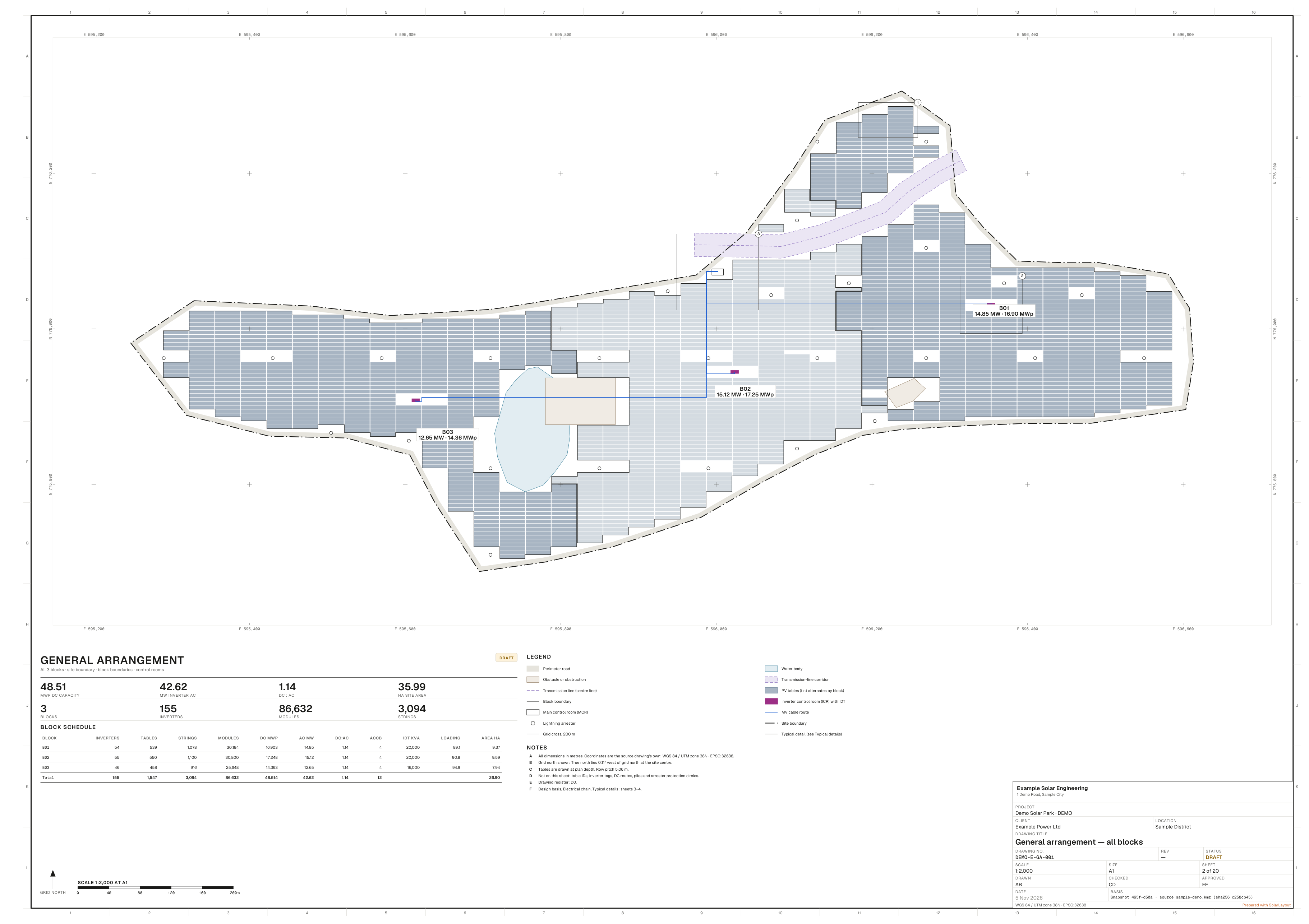
D1, general arrangement
"General arrangement — all blocks" shows the whole plant at a stated scale. Its panel holds the block schedule, a DESIGN BASIS box that points to section 3 of the design report, the ELECTRICAL CHAIN from string to grid, up to three typical details and lettered notes.
The notes say what the sheet leaves out: "Not on this sheet: table IDs, inverter tags, DC routes, piles and arrester protection circles."
D2, block layout
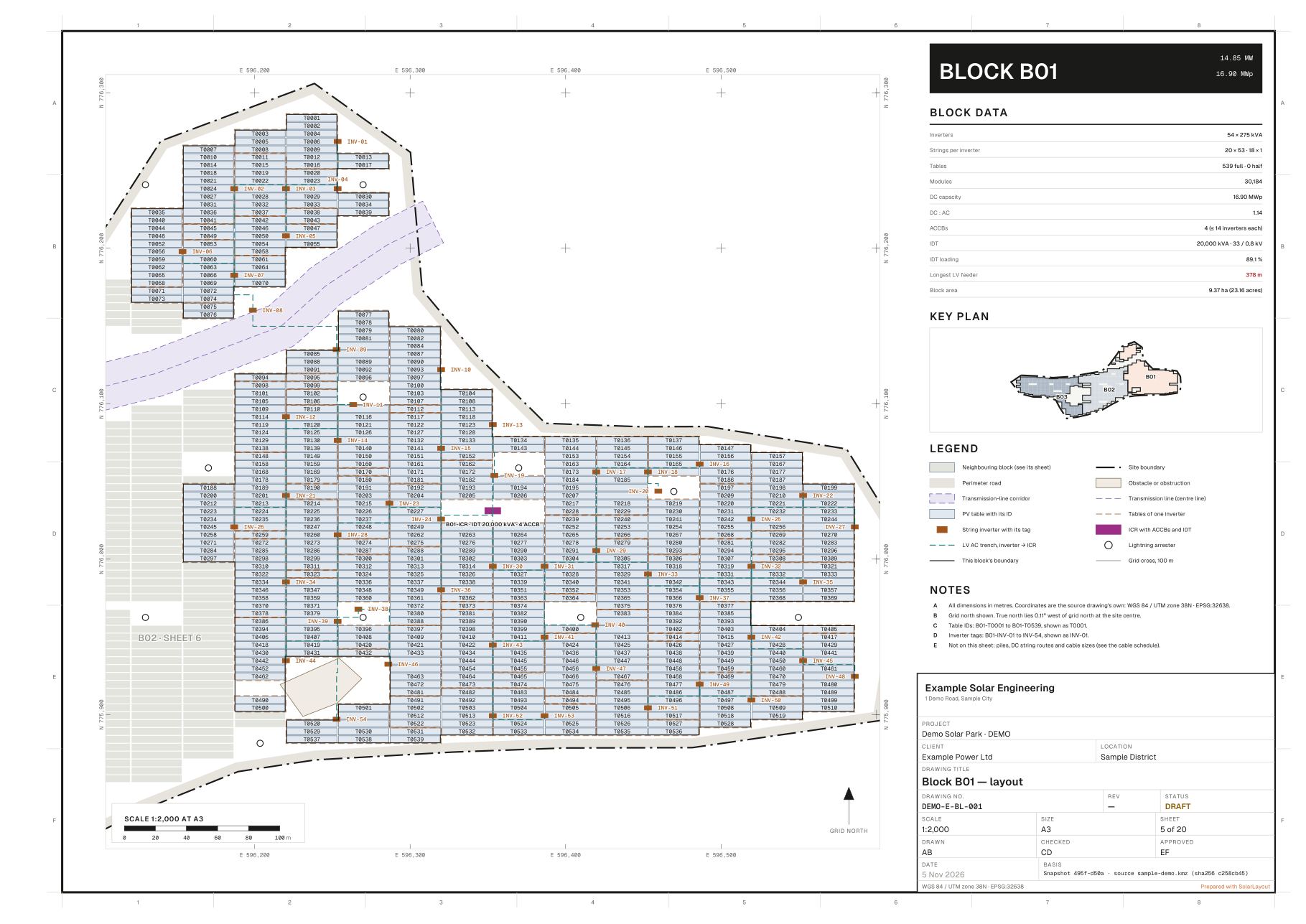
One sheet per ICR block at one scale for the whole set, each with the block's data and a key plan. Tables carry their IDs, or row ranges where the IDs are too small to print, and the sheet shows inverter zones. A large block splits into tiles with match lines: "Block P2-B01 — layout · tile 1 of 2".
"Not on this sheet: piles, DC string routes and cable sizes (see the cable schedule)." Sizes are in the schedules workbook.
D4, pile layout
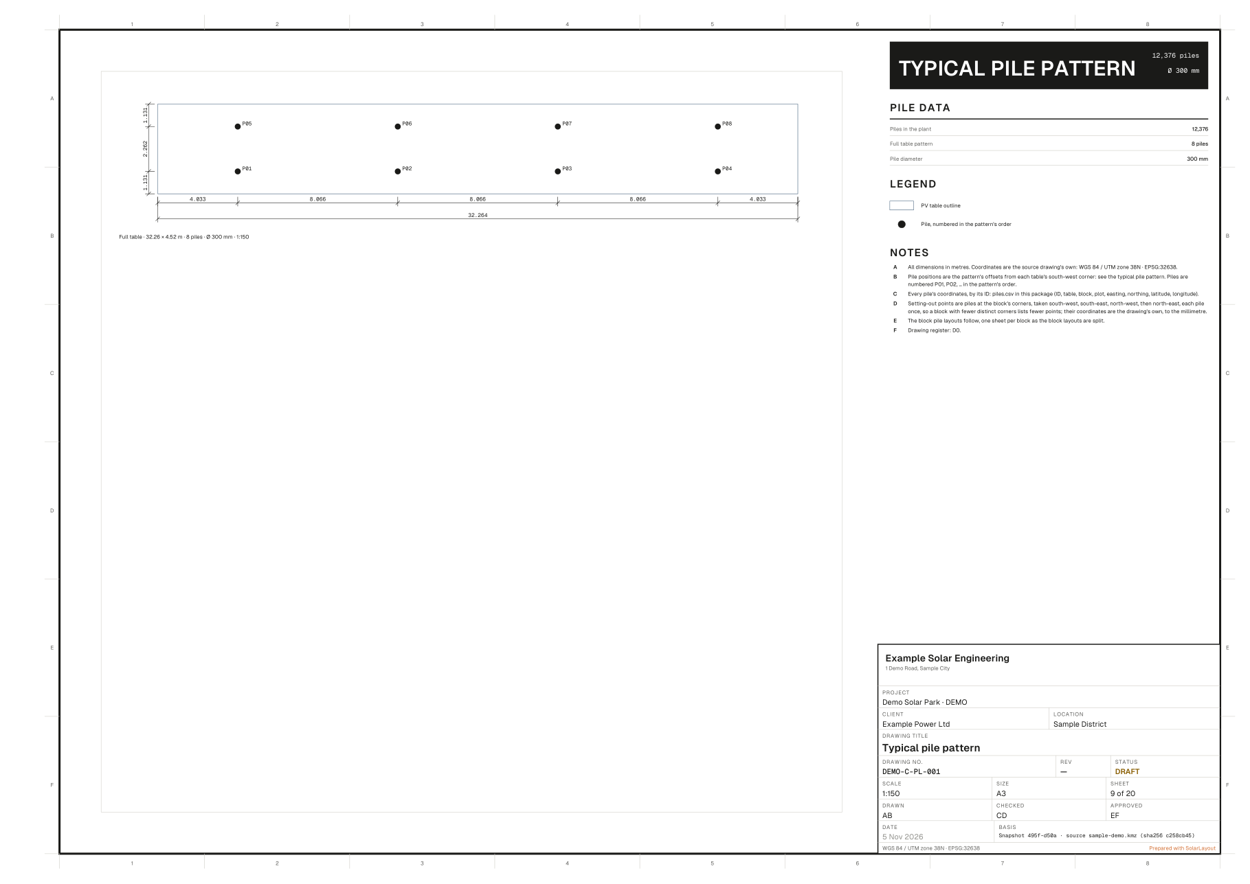
Drawn whenever a pile pattern is defined, whatever the Piles overlay on the plot says.
The Typical pile pattern sheet dimensions the pattern at 1:150, for full and half units, with its PILE DATA.
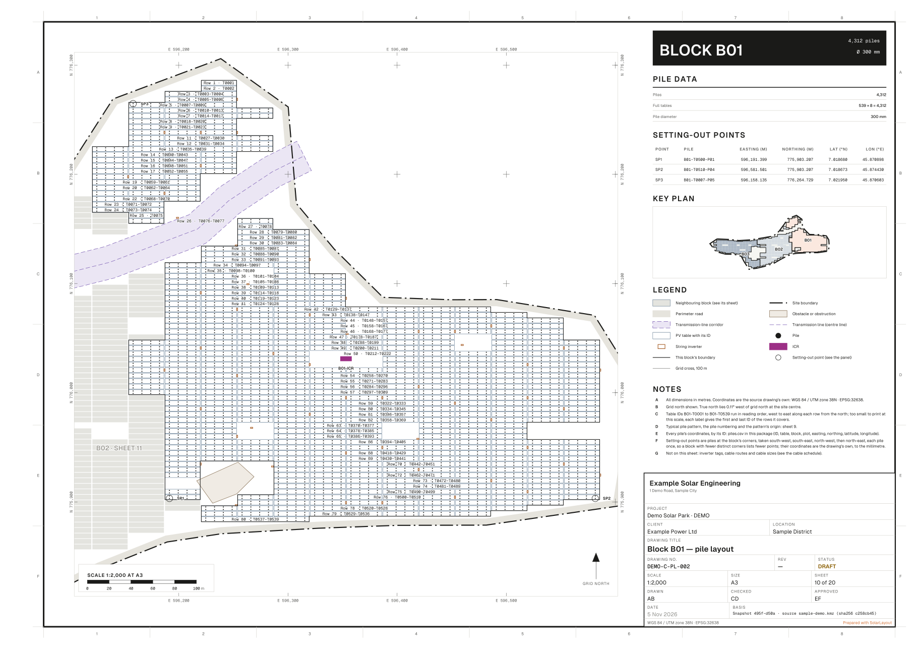
The block sheets follow the D2 tiles. Each draws a dot per pile and lists the
setting-out points SP1, SP2 and SP3 with their pile ID, easting, northing,
latitude and longitude. For every pile's coordinates, use
piles.csv, which is written
beside the drawings.
D6, earthing layout
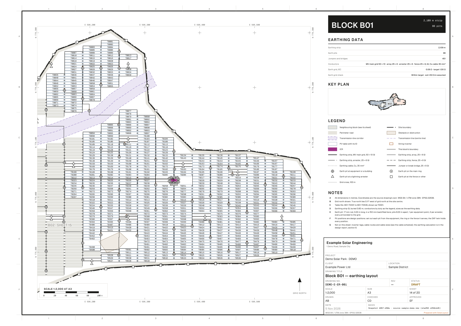
Drawn from the project's earthing design, one sheet per D2 tile. The panel gives the block's earthing strip in metres, its earth pits and conductors, the earth grid (IEC Ω against the target) and the earth grid check, with a legend by duty. While soil resistivity is unmeasured the sheet says "Soil resistivity not measured: checked once a value is entered".
D5, single line diagram
The automatic diagram, from the grid to each ICR's PV array, with a rating on every device. "Single line diagram — plant overview" comes first, then a typical block A, B and so on, one for each kind of block. Tables that overflow get sheets of their own.
Where a value isn't in the design the sheet prints "Not designed" or "by others": "A rating marked Not designed needs the inverter's datasheet."
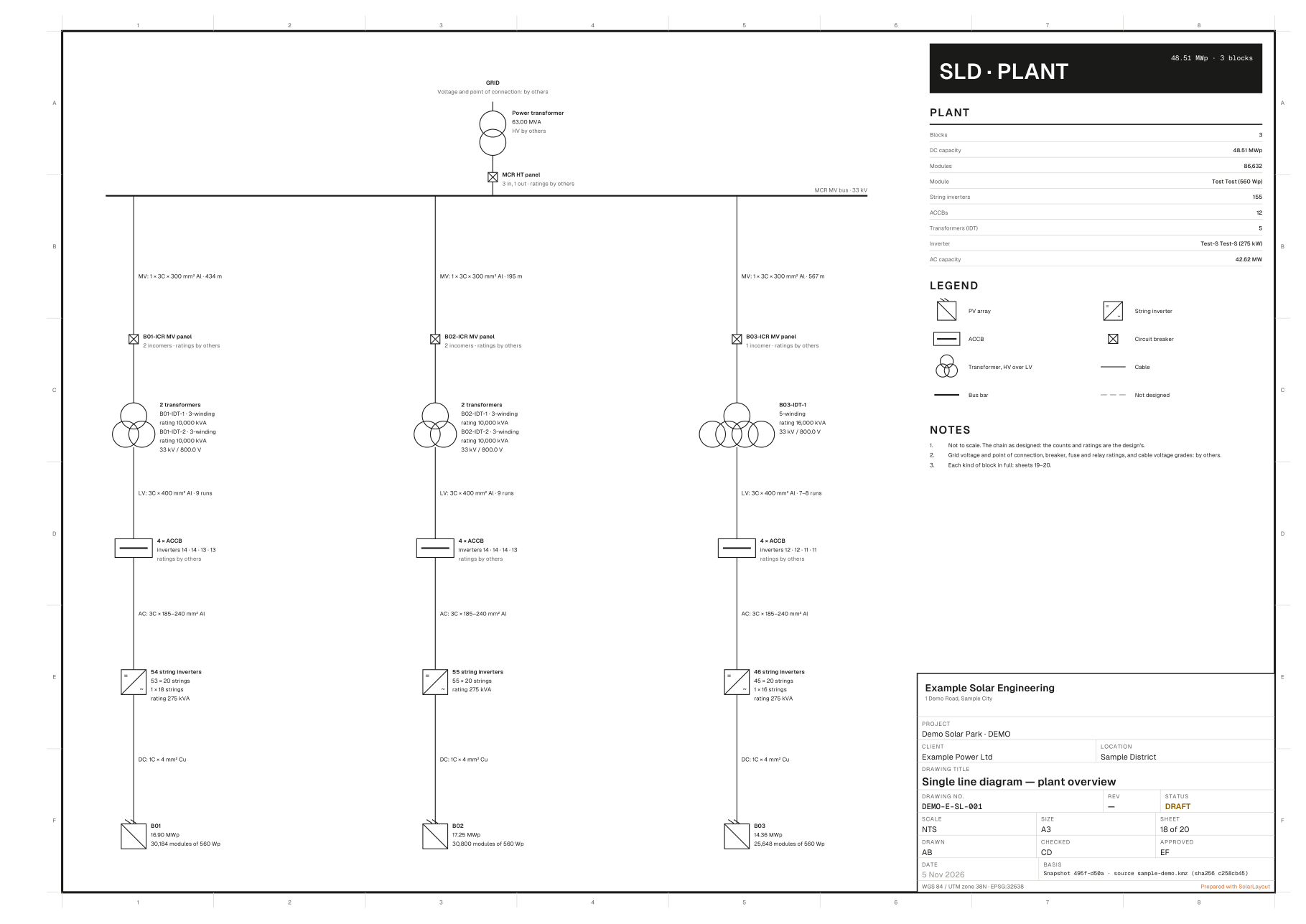
D5 is always the automatic diagram. A diagram you edited or traced in the SLD view does not reach the package, and the package doesn't wait for it. It leaves through PDF… or DWG… on the SLD view's Export card. See Exporting the diagram.
The DXF twin
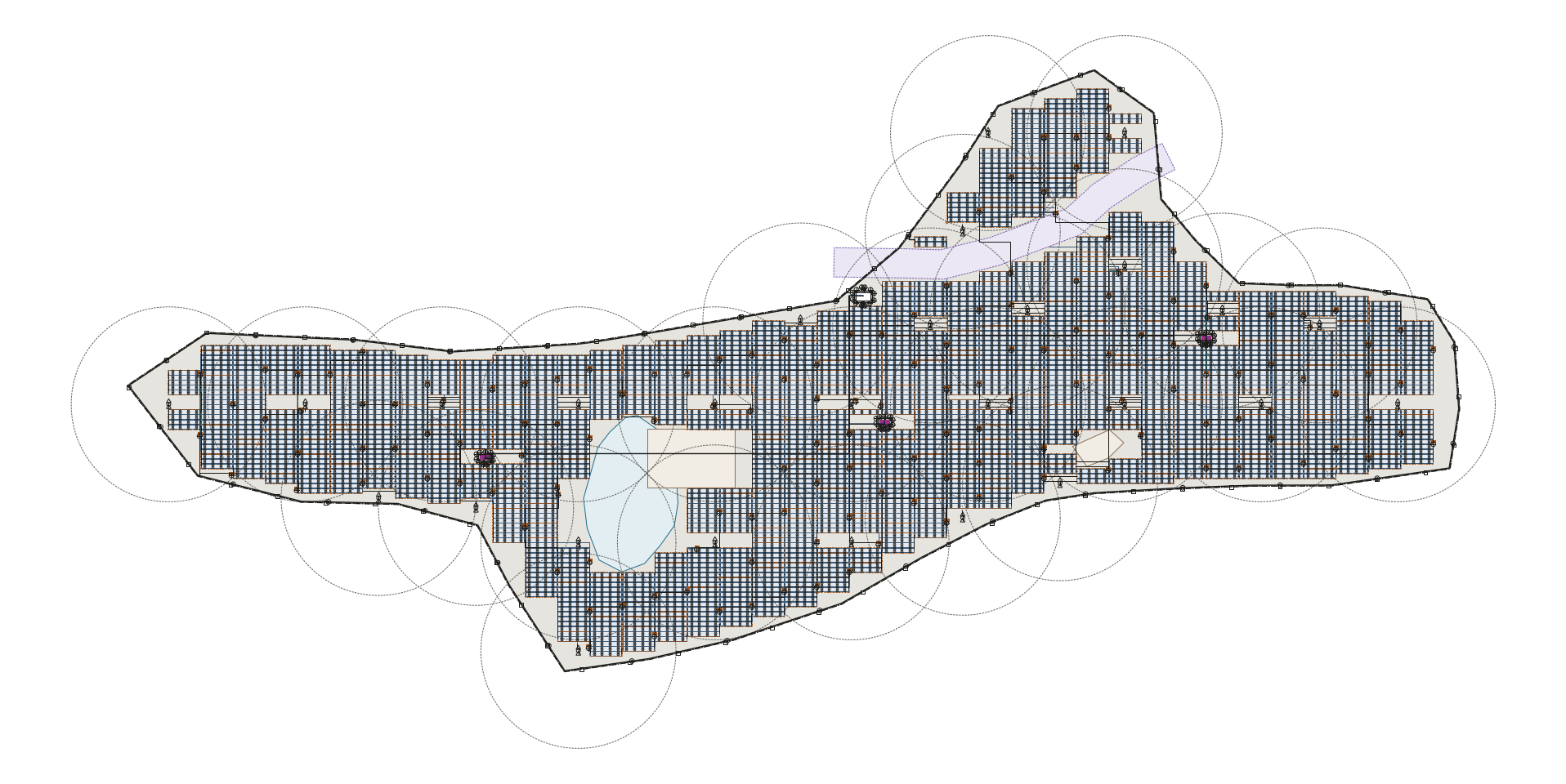
The DXF holds the same set for a CAD user. It is written in R2010 format, in metres, with Arial text.
- Model space holds the design once, in the drawing's own coordinates: UTM for a KMZ site or a drawing located by its own coordinates, and the source drawing's coordinates for a CAD or image boundary placed by hand or continued as layout only, so it overlays that drawing.
- There is one paper layout per sheet, named by its drawing number. Viewports are at the sheet's scale, with the layers that sheet doesn't draw frozen.
- Sheets name
grayscale.ctbas their plot style. - When the site is located, the file carries its geographic location.
- Writing the same snapshot on the same date gives the same file, byte for byte.
Layers
Layers use standard names, and a layer is written only when something uses it. Among them:
| Layer | Holds |
|---|---|
C-SITE-BNDY | The site boundary |
C-ROAD-PERI | The perimeter road |
C-SITE-EXCL-OBST, C-SITE-EXCL-TLCR, C-SITE-EXCL-WATR | Exclusions: obstacles, transmission-line corridors, water |
C-BLDG | Buildings |
E-PV-TABL | Tables |
E-PV-ZONE | Inverter zones |
E-INVR | Inverters |
E-IDT | Inverter-duty transformers |
E-ERTH-* | The earthing design, with every pit's position |
E-SLD-* | The single-line diagram |
G-ANNO-* | Annotation |
G-BLCK-… | Blocks |
Blocks and attributes
| Object | In the file |
|---|---|
| Tables | Blocks without attributes, one per table shape, such as PV-TABLE-32180x4728. Table IDs are not written |
| Devices | Blocks with ID, block, strings and kWp as attributes |
| Buildings | Carry their ID |
| Piles | A pattern block per table type |
| Title block | One attribute block on each sheet |
What the twin leaves out
The twin holds the design, not your drawing marks. Cable routes you drew by hand are in it. Sketch annotations, dimensions and layers you made, street lights and terrain contours are not. It carries no logo: the company's name prints instead.
The earthing drawing on its own
Export ▾ ▸ Earthing layout (DXF)… writes the earthing plan as a separate drawing, without writing a package. Export DXF… in the Earthing Design window does the same from there. See Earthing design.