CAD drawing export
The layered drawing export — every layer and what it carries, why coordinates are in metres, and which layers are conditional on your settings.
The CAD drawing export writes the plant as a layered drawing: the boundary, the exclusions, the tables, the equipment, the cables, the trenches and your annotations, each on a layer of its own. It is the deliverable for a drafting or engineering team — the people who will take the layout apart, dimension it, add their own details and issue construction drawings from it.
It is not a picture of the layout. The report's drawing page is that. This file is geometry a drafter can work in, at true size, with everything separable.
Who it is for, and what they get
| Recipient | What the layers give them |
|---|---|
| A drafting team | Separable geometry to dimension, annotate and issue |
| A civil engineer | The boundary, the excluded ground and the contours, without the electrical clutter |
| An electrical engineer | Cable routes and trench routes, by type, without the structures |
| A survey or setting-out team | Real coordinates that can be checked against a survey |
Anyone who only needs to look at the layout is better served by the Google Earth export or the report — neither needs CAD software.
Coordinates are real, in metres
Every coordinate in the drawing is in metres, in the site's own projected coordinate zone — the local UTM zone. The application works in that zone internally and converts only at the edges, so nothing is scaled, fitted or normalised on the way out.
Three consequences, all of them the point:
- The drawing is at true size. A distance measured in CAD is the distance on the ground, in metres. No drawing scale factor has to be applied or remembered.
- It can be referenced against a survey. Open the drawing alongside survey data in the same UTM zone and the two overlay directly, with no fitting step.
- It can be set out from. A coordinate read off the drawing is a coordinate a setting-out crew can use.
Check the zone before combining the drawing with anything else. Survey data supplied in a different projection, in feet, or in a local site grid will not overlay, and the mismatch is easy to miss because both drawings look plausible on their own.
The layers
Grouped below by what they belong to. The layer names are exactly as they appear in the drawing's layer list.
Site
| Layer | Carries | Colour |
|---|---|---|
BOUNDARY | The plant boundaries | Yellow |
PERIMETER_ROAD | The road setback band, as two outline polylines with no fill | Grey |
OBSTACLES | Exclusion zones from the boundary file | Red |
WATER | Water bodies | Light blue |
OBSTRUCTIONS | Obstructions you drew yourself | Green |
TERRAIN | Reduced-level contour lines | Grey |
The kept-clear ground arrives as separate layers rather than as one. OBSTACLES and WATER
are treated differently on site — a building or a substation is an obstacle to be
worked around, a pond is a water body with its own consequences — and
OBSTRUCTIONS holds what you drew by hand rather than what the boundary file
declared, so a recipient can tell the two apart. See
Obstructions.
PERIMETER_ROAD is the band between the plant boundary and the usable area, and
it comes across as two outline polylines with no fill — the outer edge and the
inner edge. A drafter therefore receives the road reserve as boundaries to work
with rather than as a solid to delete, and the same band is the one drawn on the
plot and in the report. See
How placement works.
Array
| Layer | Carries | Colour |
|---|---|---|
TABLES | Every placed module table or tracker unit | Blue |
One layer for the whole array. Switch it off and the site, the equipment and the cabling are all still there — which is how a drafter works on anything other than the modules.
Tables are written as block references, not as individual outlines. Every
table of a given size is an insert of one shared block definition, so editing that
block in your CAD program updates every table in the plant at once. The block's
own geometry sits on layer 0, so each insert takes the properties of the layer
it is placed on, which is standard CAD practice. Tell the drafting team: a change
to the table detail is one edit, not tens of thousands.
Equipment
| Layer | Carries | Colour |
|---|---|---|
ICR | The inverter control rooms | Cyan |
MCR | The main control room | Violet |
INVERTERS, or SMB in Central Inverter mode | The string inverters, or the string monitoring boxes | Lime |
OBJECTS | The objects you placed | Brown |
STREET_LIGHT | The street-light poles | Orange |
LA | The lightning arrester symbols | Maroon — written only when arresters were placed |
The equipment layer name follows the electrical mode. In a Central Inverter design
the layer is named SMB and carries the string monitoring boxes, because the
central inverters themselves sit inside the control room rather than out among the
tables. See Inverter control rooms.
Keep-clear shadows
| Layer | Carries | Colour |
|---|---|---|
ICR_MCR_SHADOW | The year-round keep-clear shadow of the control rooms | Grey |
OBJECT_SHADOW | The keep-clear shadow of the placed objects | Grey |
STREET_LIGHT_SHADOW | The keep-clear shadow of the street lights | Grey |
Three layers a recipient will otherwise mistake for stray hatching. Each one is the ground a structure shadows across the shadow window — and with Clear tables inside shadows on, which is its shipped state, that is the ground the tables were cleared from. The shadow layers are therefore the justification for the gap in the array beside every building, object and pole. Keeping them separate means a drafter can show that justification or switch it off, and a civil engineer can see which cleared ground is shadow rather than obstruction. See Structures and shadow.
Cables
| Layer | Carries | Colour |
|---|---|---|
DC_CABLES | DC string cables | Orange |
AC_CABLES | AC cables from the inverters | Magenta |
MV_CABLES | Medium-voltage cables, control room to main control room | Green |
Three layers rather than one, because the three are different cables with different sizes, different burial requirements and usually different contractors. All three are written only when cable calculation was on for the run — see the conditional layers below.
Trenches
| Layer | Carries | Colour |
|---|---|---|
DC_TRENCH | DC trench routes | Green |
AC_TRENCH | AC trench routes | Red |
MV_TRENCH | Medium-voltage trench routes | Dark green |
A trench and a cable are not the same length, and that is why they are on separate layers. Several cables share one trench, so trench routes are the de-duplicated routes on the ground while the cable layers carry the conductor runs. The trench layers are what a civil contractor prices and excavates. See Cable routing.
Drafting
| Layer | Carries | Colour |
|---|---|---|
SKETCH | All Sketch Mode annotations | White |
ANNOTATIONS | Labels and text | White |
- What it shows
- A CAD program with the exported drawing open and the layer panel visible, so the layer names can be read against the drawing.
- How to get there
- Export the drawing file and open it in AutoCAD or BricsCAD, and show the layer manager. The frame is the CAD program, not the save window.
- Callouts to add
- Outline the layer list.
Three layers that may be absent
Most of the layers above are written on every export, whether or not they have anything in them. Three are conditional, and a layer that is not in the file is usually a setting you chose rather than a fault in the export.
| Conditional layer | Written when | Colour |
|---|---|---|
DC_CABLES, AC_CABLES, MV_CABLES | Cable calculation was on for the run | Orange, magenta, green |
LA | Lightning arresters were placed | Maroon |
PILES | A pile pattern has been defined | Orange |
The first two settings are off by default and no pile pattern exists until you define one. So a first export, produced from a first run at the defaults, has no cable layers, no arrester layer and no pile layer — and that is correct behaviour rather than a missing export. Piles are defined in the pile layout editor; see Piles.
If the recipient needs cable and trench routing, tick Calculate Cables for PV Power Plant and generate again before exporting. Cable calculation is the slow step on a large plant, which is why it is off to begin with — the recommended order is to review the layout first, then enable it for the final run.
Your annotations come across
Everything you drew in Sketch Mode — the lines, polylines, rectangles, circles,
arcs, splines, fills and dimensions — is written to the SKETCH layer, and the
labels and text land on ANNOTATIONS.
Keeping them on their own layers is deliberate, and it is worth telling the recipient: your working notes, sketched intent and markup are separable from the plant. They can switch the layers off and have the plant with none of your commentary on it, or leave them on and read what you were pointing out. Neither requires them to delete anything.
The layers you create in Sketch Mode do not become CAD layers. The exported
layer set is fixed to the ones listed above, so every annotation lands on the
single SKETCH layer whichever in-application layer it was drawn on. If the
recipient has to be able to separate one set of markup from another, distinguish
them by colour or by a text label, or issue them as separate exports — the layer
structure will not carry the distinction across.
See Annotations for the drawing tools themselves.
Before you export
Turn cable calculation on, if routing is needed
Generate again with Calculate Cables for PV Power Plant ticked. Without it there are no cable layers, the trench layers hold nothing but what you drew by hand, and a trenching estimate cannot be made from the drawing.
Finish the layout edits
Hand-placed tables, deleted tables, drawn obstructions, moved control rooms and hand-drawn trenches all export, so make them before you write the file rather than after. See Sketch Mode.
Clear the annotations you do not want issued
Anything left in Sketch Mode goes into the file on the SKETCH layer. It is
separable, but it is still in the drawing. 🗑 Clear Annotations removes it.
Export the drawing
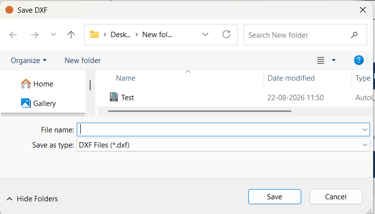
Click Export DXF in the export block beside the plot. Choose the folder and
the file name; the file type is fixed to .dxf.
Open it and check the layer list
Open the file and read its layer list against the tables above. This one check catches the common surprises immediately — no cable layers because the run had cables off, no arrester layer because arresters were off, no pile layer because no pattern was defined. All three are fixed before the export, not by exporting again.
Limits
- It is geometry, not a drawing set. There is no border, no title block, no drawing number and no revision block. Those are the recipient's, in their own template.
- Nothing is dimensioned unless you dimensioned it. The dimensions in the file are the ones you drew in Sketch Mode.
- It carries no quantities. Take those from the bill of materials rather than counting entities in CAD.
- The single-line diagram is exported separately. It is not part of this file. See Exporting the diagram.
Where to go next
Google Earth export
The layout written as a Google Earth file — one folder per plant, the summary placemark, and how to check the design against real ground.
Saving and reopening projects
The .slp project file keeps a whole working session — inputs, layout, hand edits, diagram and materials list — and refuses to load if it has been altered.