Plant layout and SLD
The plant designer's two tabs, its shared input form, and the auto-placement engine behind Generate Layout and Generate SLD.
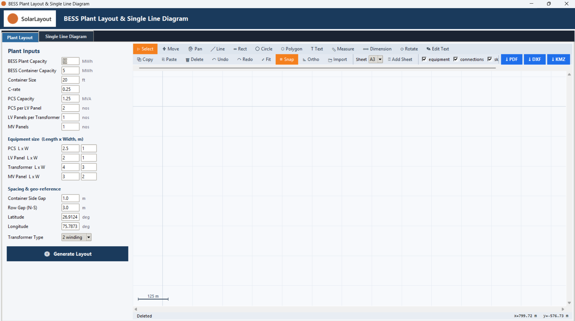
Run ▸ BESS Plant Layout & SLD… — or the banner 🏗 Plant Layout & SLD button — opens a separate window for laying out a BESS plant's equipment and drawing its single-line diagram. Two tabs, Plant Layout and Single Line Diagram, share one input form and the same auto-placement engine, so whatever you set on one tab is what the other builds from.
The two tabs
Plant Layout shows the input form on the left, alongside a drawing canvas. Single Line Diagram reuses the same inputs — it shows only the note Uses the same inputs as the Plant Layout tab. in place of a form — and has its own drawing canvas. Each canvas has its own toolbar, so the tool in use, the undo history, snap/ortho and layer visibility are independent between the two. See The drawing editor.
The shared input form
The form is split into three groups.
The first group sets the plant's equipment counts and ratings:
| Field | Default | Range | What it does |
|---|---|---|---|
| BESS Plant Capacity | 10 MWh | — | Total battery energy capacity for the plant; sets the number of containers |
| BESS Container Capacity | 5 MWh | — | Energy capacity of one battery container |
| Container Size | 20 ft | — | Container length; looked up in a standard container-size table (20/40/45 ft), or scaled from the 20 ft ratio for any other length, to size the container's footprint |
| C-rate | 0.25 | — | Power ÷ energy sizing ratio for the BESS; unitless — C-rate is also set independently on Battery parameters |
| PCS Capacity | 1.25 MVA | — | Power rating of one PCS (power-conversion system) unit |
| PCS per LV Panel | 2 nos | — | PCS units combined onto each LV panel |
| LV Panels per Transformer | 1 nos | — | LV panels feeding each transformer; also auto-syncs Transformer Type below |
| MV Panels | 1 nos | — | Number of MV panels, fed by all transformers |
The second group, Equipment size (Length x Width, m), sets each equipment type's footprint as a paired length and width:
| Field | Default (L × W, m) | Range | What it does |
|---|---|---|---|
| PCS L x W | 2.5 × 1 | — | Footprint of one PCS unit |
| LV Panel L x W | 2 × 1 | — | Footprint of one LV panel |
| Transformer L x W | 4 × 3 | — | Footprint of one transformer |
| MV Panel L x W | 3 × 2 | — | Footprint of one MV panel |
The third group, Spacing & geo-reference, sets the gaps between equipment and the site's coordinates:
| Field | Default | Range | What it does |
|---|---|---|---|
| Container Side Gap | 1.0 m | — | Gap left beside each container |
| Row Gap (N-S) | 3.0 m | — | North–south gap between rows |
| Latitude | 26.9124 deg | — | Site latitude — the georeferencing anchor for importing or exporting a KMZ/KML background |
| Longitude | 75.7873 deg | — | Site longitude — the georeferencing anchor for importing or exporting a KMZ/KML background |
An east–west gap between transformer groups is set automatically as Container Side Gap plus 4.0 m; it has no field of its own.
A separate Transformer Type control sets the transformer's winding configuration:
| Field | Default | Range | What it does |
|---|---|---|---|
| Transformer Type (2 winding / 3 winding / 5 winding) | 2 winding | 2 winding, 3 winding, 5 winding | Read-only; auto-syncs from LV Panels per Transformer — 1 → 2 winding, 2 → 3 winding, 4 → 5 winding. Any other count leaves the previously chosen type unchanged |
Generating and drawing
⚙ Generate Layout and ⚙ Generate SLD both auto-place the plant's equipment from the form above — the first as a scaled layout, the second as schematic symbols on the same topology. From there, each tab's drawing tools let you move, add to or correct what was placed, and each canvas exports to PDF, DXF or KMZ on its own. See the pages below.